Fluid power includes either gas (such as air) or hydraulic (such as water or oil) motive media.
Fluid power systems are divided into five basic components:
• Pumps
• Reservoirs
• Actuators
• Valves
• Lines
Pumps
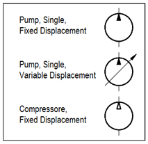
Hydraulic pumps are shown by solid arrow heads.
Pneumatic compressors are represented by hollow arrow heads.
Reservoirs
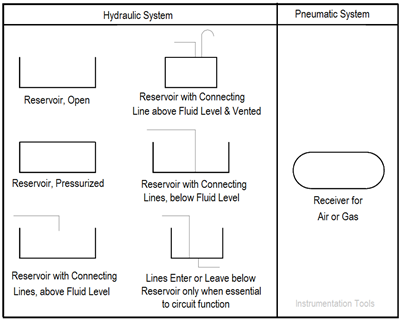
Reservoirs provide a location for storage of the motive media (hydraulic fluid or compressed gas).
- Pneumatic reservoirs are usually simple tanks.
- Hydraulic reservoirs are complex in terms of how the fluid is admitted to and removed from the tank.
Actuator
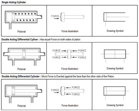
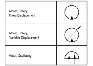
An actuator is a device that converts the hydraulic or pneumatic pressure into mechanical work.
Actuators are classified as:
- Linear actuators (Have some form of piston device)
- Rotary actuators (Are generally called motors and may be fixed or variable)
Valves
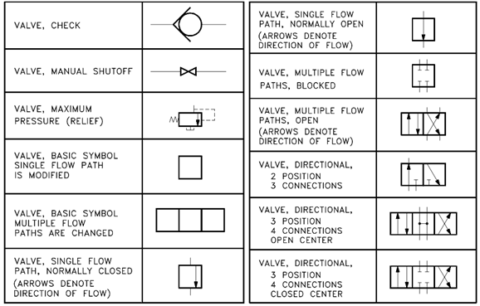
Valves provide the control that is required to route the fluid to the correct point when needed.
Valve representation in Fluid power system is more comprehensive than as used in standard P&IDs. In a typical P&ID, a valve opens, closes or throttles the process fluid, but is rarely required to route the process fluid in any complex manner (3 & 4 way valves being the common exceptions). In fluid power systems it is common for a valve to have three to eight pipes attached to the valve body, with the valve being capable of routing the fluid, or several separate fluids, in any number of combinations of input and output flowpaths. Fluid power valves, when electrically operated by a solenoid, are drawn in the de-energized position.
Lines/ Piping
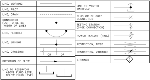
Piping in a fluid power system is to transport the working media, at pressure, from one point to another.
Reference: InstrumentationTools
